PDE Perspectives on a new type of measurement for future aircraft wings and turbines
Product Design Engineering (PDE) Program embarks students for their future career in any possible products, including aircraft domain. PDE is applicable as well in the product design for the future aircraft wings and turbines. More efficient aircraft and wind turbines will need more accurate aerodynamic profiles, in particular in design process until its production stage.
Source: https://www.imeche.org/
FEATURE: A new type of measurement for future aircraft wings and turbines
03 Mar 2020
Dr Jody Muelaner

More efficient aircraft and wind turbines will need more accurate aerodynamic profiles.
This will require a step change in large-scale measurement accuracy. The National Physical Laboratory (NPL) is developing a state-of-the-art measurement technique, originally invented for the Large Hadron Collider, into an instrument that may provide this. The lab’s divergent beam FSI system promises to allow self-calibrating and highly accurate coordinate measurements of multiple targets simultaneously, with direct traceability to the SI meter.
Large-scale coordinate measurements are often required in industries such as aerospace. Targets are placed on jigs, product features and production machinery. Two types of instrument are currently used to measure these targets – laser trackers and photogrammetry.
Laser trackers are often the most accurate and the most convenient. They consist of a columnated laser mounted within a gimbal arrangement. The laser measures the distance to the target, using an interferometric or absolute distance measurement technique, while angle encoders within the gimbal measure the direction to the target. This gives the target position in spherical coordinates, which are often converted to Cartesian coordinates for convenience. As the name suggests, a control system, with motors within the gimbal, enables a laser tracker to track a moving target. This enables an operator to conveniently move the target around while the laser tracker continuously measures its location.
One issue with these instruments is that the columnated beam that they use can only measure one target at a time.
Photogrammetry uses digital images of multiple targets, captured from multiple positions. This enables target coordinates to be determined by triangulation, assuming that the distance between at least two targets or camera positions is known so that scale can be determined. Photogrammetry can monitor multiple targets and track them at high frequency, although there is a compromise between accuracy and speed. As any photographer will know, as shutter speed is increased there is an increasing compromise between light sensitivity, depth of field and image noise. For photogrammetry this means reduced measurement accuracy.
A fundamental limitation with both laser trackers and photogrammetry is the way that rays of light are distorted by the environment, especially temperature gradients in the air. As a beam of light propagates through the air, the refractive index changes depending on environmental factors such as temperature, pressure, humidity and carbon dioxide concentration.
Variation in the refractive index, along the path of a laser, will mean that the carefully corrected calculation for the laser wavelength will not be correct. The wavelength calculation can only be based on measurements of environmental parameters at a few locations, typically just at the laser itself. Identifying the average wavelength along the path is usually not possible, introducing uncertainties into the laser distance measurement. Any gradients in the refractive index perpendicular to a ray of light will cause the ray to bend slightly, distorting the coordinates measured by both laser trackers and photogrammetry. This effect can be clearly observed on a hot day, or close to a heat source such as an engine exhaust. This is commonly referred to as a heat haze or a mirage, and very noticeable distortions can be seen.
Invisible distortions
Under more common conditions within a production facility, these distortions are not observable with the naked eye but are often the dominant source of uncertainty for laser tracker and photogrammetry measurements. Laser trackers may minimise environmental disturbances by measuring targets from multiple positions so that distance measurements can be combined in a process known as multilateration. However, this can significantly increase measurement time.
The aerospace industry in particular requires a more accurate and faster way to measure coordinates at large scales. Reducing the fuel burn of aircraft means improving their aerodynamic efficiency, with manufacturers aiming for natural laminar flow wings in the next generation of civil aircraft. This will require measurements that are approximately an order of magnitude more accurate than what is achievable with a laser tracker.
Increasing production rate and reducing manufacturing cost will require a much faster assembly process. Achieving part-to-part interchangeable assembly will also require a step change in large-scale measurement accuracy. These improvements cannot be made without a fundamental change in the way that measurements are made so that environmental disturbances are no longer the limiting factor.
Large Hadron Collider
When the Large Hadron Collider was being built at the CERN particle physics laboratory, it became apparent that a new measurement system would be needed to monitor the particle detector positions to within 1 micrometre over distances of tens of metres. Researchers from the University of Oxford developed a technique known as Frequency Scanning Interferometry (FSI) which uses a tunable laser to provide highly accurate distance measurements.
The laser is split and fibre channelled to allow hundreds of individual distances to be simultaneously monitored using a single laser source while dual lasers for each distance provide corrections for changes in the refractive index. Fourier transform analysis of the returned light then allows the signals from multiple lines to be sorted out so that each distance can be uniquely determined.
One practical limitation with the system at CERN is that columnated laser beams were used. These had to be accurately aligned for each target. It worked fine for long-term monitoring of a set of particle detectors, but would have been less convenient within industry.
NPL’s divergent beam FSI
NPL set out to apply the highly accurate and cost-effective FSI technique to a practical and versatile measurement instrument that is suitable for large-scale manufacturing. Professor Ben Hughes, senior scientist at NPL, explains: “The idea was prompted by discussions with end-users of portable coordinate measurement systems who often asked us about how they could be sure the system was operating within specification and, if it was, how accurate it was or what would the measurement uncertainty be. These are difficult questions to answer in general, so we decided to see if we could develop a system that calibrated itself and provided measurement uncertainty estimates for every coordinate measured.”
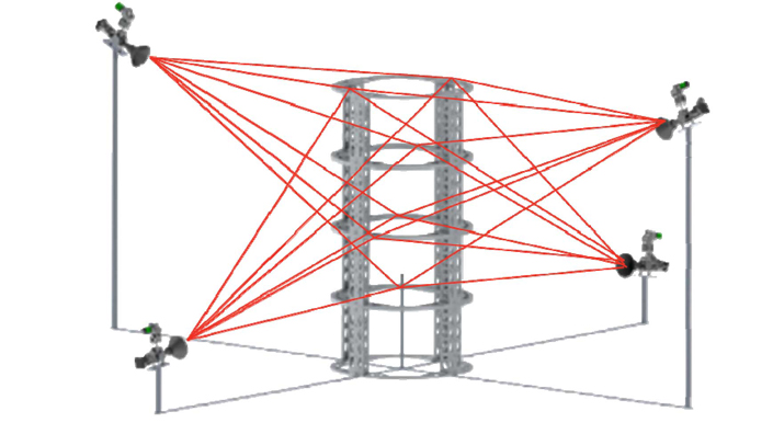
NPL’s key innovation is to enable a single measurement device to simultaneously direct laser beams to multiple targets.
The divergent beam FSI system consists of a single FSI unit, containing a laser and signal processing, sensor units, and retroreflective glass spheres used as targets. Each sensor is able to measure the distance to multiple targets, so that accurate coordinates can be determined by multilateration. Dynamic targets will be tracked at 30Hz with an accuracy of tens of micrometres.
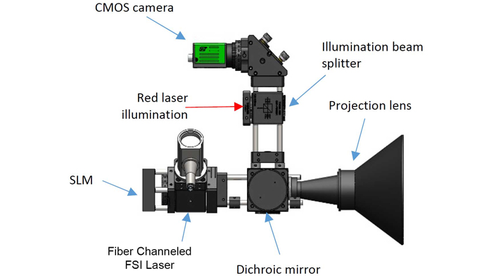
 A single NPL sensor identifies the targets with a CMOS camera and automatically aims beams at all of the targets using a Spatial Light Modulator
 Each sensor can detect the direction of multiple targets and then measure their distance using FSI, a technique first developed to measure movements of the particle detectors in the Large Hadron Collider
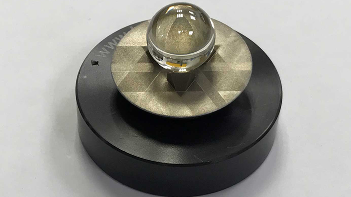
 The retroreflective targets are spheres made from a special glass with a refractive index of two
Each sensor contains a low-cost illumination laser, which is projected through a divergent lens to illuminate all of the targets. Laser light reflected by the targets is returned to the sensor through the same lens and directed to a CMOS camera by a beam splitter. This camera identifies the direction of each target, enabling measurement beams to be directed to them.
The sensor unit receives the FSI measurement laser through a fibre-optic channel from a central laser source. The FSI laser is then directed through a Spatial Light Modulator (SLM) and then through the divergent lens. The target directions are used to control the SLM so that it generates a beam directed at each target. Each of these beams is directed back to the sensor by the retroreflective targets and then in turn directed into the fibre channel to be processed by the central FSI detector. This determines each distance uniquely using Fourier transform analysis. A dichroic mirror, which is a wavelength-dependent beam splitter, ensures that the illumination and FSI lasers are directed to the appropriate detectors.
Licensing plan
Hughes says: “The main advantages of combining FSI with multilateration are that the system can be made directly traceable to the SI meter, can calibrate itself as an inherent part of the measurement process and it can provide rigorous measurement uncertainty estimates taking into account environmental conditions such as vibration and air temperature gradients.”
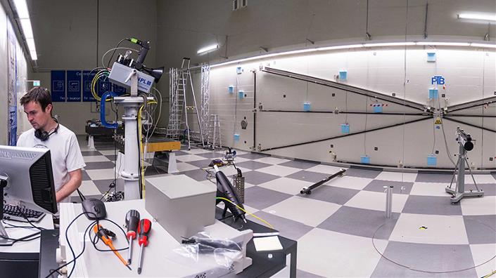
The prototype divergent beam FSI system, currently being developed at NPL, is able to measure targets within a 10 x 10 x 5m volume, although it is anticipated that this will be significantly increased. Further developments are also required towards a robust and practical industrial system and it is hoped that it will be ready to license to manufacturers within one or two years.
Want the best engineering stories delivered straight to your inbox? The Professional Engineering newsletter gives you vital updates on the most cutting-edge engineering and exciting new job opportunities. To sign up, click here.
Content published by Professional Engineering does not necessarily represent the views of the Institution of Mechanical Engineers.

Comments :